
Big Picture:
Networking is an area of computer science where I could always improve my understanding. This article will mark the beginning of my journey and will cover fundamental networking concepts including networking topologies, mediums, and protocols that can be used to facilitate a network and enable computers to talk to each other. A high level way to think about networking is that a home computer could be sending packets and we can think of these packets like letters. Letters go to the post office (Router) that go to the main post office (Internet Service Provider) and that looks in the address register (Domain Name System) and the address for the desired recipient (IP address) if found and the letters (Packets) are sent. Then this communication is reversed.
When considering a corporate network and how it should be structured there are some key points to keep in mind:
- A web server (hosting a company site) should be on an isolated Demilitarized Zone since it’s internet facing leading to a greater likelihood of compromise
- Workstations should be on their own network and, ideally, have their own host-based firewall rule preventing them from taking over other workstations. When workstations are on the same network as the server, attacks like spoofing and on-path attacks are more likely.
- Switches and Routers should be on their own Admin network” to prevent workstations from snooping in on any communication between these devices.
- Printers and phones should be on their own networks because they are harder to secure and this also helps reduce traffic on other, more important networks.
Networking Structure
Network Types
- WAN
- Wide Area Networks are the Internet. Devices often have a WAN and LAN address with WAN being accessed by the internet and LAN being internal. WAN is just a large number of LANs that are joined together. WANs can be identified if they use WAN specific protocols like BGP or if the IP Schema is not within LAN ranges.
- LAN/WLAN
- These networks will have devices with IP addresses assigned with the LAN IP Schema (RFC 1918) e.g. 10.0.0.0/8, 172.16.0.0/12, 192.168.0.0/16. WLAN’s are the same as LAN’s with the exception that they can transmit data without cables
- VPNs
- Site-To-Site VPN
- Both the client and the server are typically network devices (Routers or Firewalls) and they share entire network ranges. This VPN is commonly used to join company networks together over the internet to enable communications as if they were local.
- Remote Access VPN
- This involves a client’s computer creating a virtual interface that behaves as if it is on a client’s network. One example is openVPN that creates a TUN adapter to let someone access a web server’s resources in a way where traffic does not go out to the internet.
- SSL VPN
- This is a VPN that is done within a web browser and is slowly becoming more popular.
- Site-To-Site VPN
- PAN
- A personal area network would include devices within your immediate area e.g. Bluetooth
Networking Topologies
A topology is an arrangement of physical or logical connection of devices within a network. Computers are hosts (clients and servers) that actively use the network. They include components (switches, bridges, and routers) that have a distribution to ensure all network hosts can establish connections with each other. The transmission medium layout is a mapping of physical connections between nodes and cabling. Networks generally have 8 types of topologies:
- Point-to-Point: The simplest topology featuring a direct, dedicated connection between only two hosts for mutual communication. This is the basic model of traditional telephony.
- Bus: All hosts connect to a shared transmission medium (like coaxial cable) where only one host can send at a time while others receive and check if data is intended for them. There is no central network component controlling the processes.
- Star: Each host connects to a central network component (router, hub, or switch) via separate links, and this central device handles all data forwarding. All traffic passes through the central component, which can experience high data loads.
- Ring: Each host connects to the ring with two cables (one incoming, one outgoing) and information travels in a predetermined direction using a token or retrieval system. A logical ring can be based on a physical star topology where a distributor simulates the ring by forwarding between ports.
- Mesh: Multiple nodes manage connections and routing without a fixed topology, available in fully meshed (every host connects to every other host) or partially meshed (some nodes have single connections, others have multiple) structures. Fully meshed networks are used in WAN/MAN for high reliability since the network can absorb failures through redundant connections.
- Tree: An extended star topology useful for larger networks that combines multiple topologies, commonly seen in company buildings with hub hierarchies. This structure is used for broadband networks, city networks (MAN), and follows spanning tree protocols.
- Hybrid: Created when two or more different basic network topologies are interconnected, resulting in a network that doesn’t present any standard topology. For example, star networks connected via bus networks form a hybrid structure.
- Daisy Chain: Multiple hosts are connected in series by placing cables from one node to another, creating a chain configuration commonly found in automation technology. The signal travels to and from each component through its previous nodes to reach the computer system.
Proxies
A proxy is when a device sits in the middle of a connection and acts as a mediator (meaning it inspects contents of traffic, otherwise it would just be a gateway). Forward proxies (like burp suite) send out requests and mediate outgoing traffic and a Reverse Proxy filters incoming traffic. A common Reverse Proxy could be a Web Application Firewall (WAF) that inspect web requests for malicious content to block. Pen testers and configure Reverse Proxies on infected endpoints to listen on ports and find who connects to said port and redirect them back to the attacker to bypass firewalls or evade logging. Proxies can be transparent or not, this means that users either do or don’t know of their existence.
Networking Models
There are two main networking models we know:
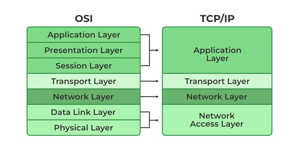
- The OSI model splits network communication between 7 layers that have their own distinct tasks.
- The TCP/IP model more-so refers to the family of protocols that are used to transfer data.
Most of the time data is sent in what is called a Protocol Data unit (PDU) and during transmission each layer adds a header to the PDU from the upper layer which controls and identifies the packet (called encapsulation). The TCP/IP model helps us understand how connections are established and data is sent and with the OSI model we can break things down by each layer. Here is the breakdown of the OSI layers:
Layer 7 – Application: This layer includes protocols that applications use directly, such as HTTP/HTTPS (web browsing), FTP (file transfer), SMTP (email sending), DNS (domain name resolution), SSH (secure remote access), and Telnet.
Layer 6 – Presentation: Handles data encoding, encryption, and compression using technologies like SSL/TLS (encryption), JPEG/GIF/PNG (image formats), MPEG/MP4 (video formats), ASCII/EBCDIC (character encoding), and data compression algorithms.
Layer 5 – Session: Manages sessions and connections using protocols like NetBIOS (network basic input/output), RPC (Remote Procedure Call), PPTP (Point-to-Point Tunneling Protocol), and SQL (database sessions).
Layer 4 – Transport: Provides reliable data transfer using TCP (Transmission Control Protocol) for connection-oriented communication or UDP (User Datagram Protocol) for connectionless communication, along with port numbers to identify specific applications.
Layer 3 – Network: Routes data across networks using IP (Internet Protocol including IPv4 and IPv6), ICMP (Internet Control Message Protocol for ping/traceroute), routers, and routing protocols like OSPF, BGP, and RIP.
Layer 2 – Data Link: Enables direct node-to-node communication using Ethernet, Wi-Fi (802.11), switches, bridges, MAC addresses, PPP (Point-to-Point Protocol), and frames for data organization.
Layer 1 – Physical: Handles the physical transmission medium including Ethernet cables (Cat5e, Cat6), fiber optic cables, hubs, repeaters, wireless radio frequencies, voltage levels, and the actual bits (0s and 1s) transmitted.
While the TCP/IP model has only four layers:
Layer 4 – Application: Combines OSI Layers 5-7 and includes protocols like HTTP/HTTPS (web), FTP/SFTP (file transfer), SMTP/POP3/IMAP (email), DNS (name resolution), SSH (secure shell), Telnet, DHCP (IP assignment), and SNMP (network management).
Layer 3 – Transport: Provides end-to-end communication using TCP (Transmission Control Protocol) for reliable, connection-oriented delivery with error checking and flow control, or UDP (User Datagram Protocol) for fast, connectionless delivery without guarantees, along with port numbers (0-65535) to identify services.
Layer 2 – Internet: Handles logical addressing and routing using IP (Internet Protocol including IPv4 and IPv6), ICMP (ping, traceroute, error messages), ARP (Address Resolution Protocol to map IP to MAC addresses), and routers to forward packets across networks.
Layer 1 – Link: Combines OSI Layers 1-2 and handles physical transmission using Ethernet, Wi-Fi (802.11), PPP (Point-to-Point Protocol), MAC addresses, network interface cards (NICs), switches, cables (copper, fiber), and the actual frame formatting for the specific network medium.
With this model IP ensures that data packets reach destination and TCP controls the transfer of data and ensures connection between the data stream and application. Here are some important tasks within TCP/IP:
Logical Addressing (IP): IP provides logical addressing to structure network topology and identify hosts across different networks using methods like network classes (Class A, B, C), subnetting (dividing networks into smaller segments), and CIDR (Classless Inter-Domain Routing) notation like 192.168.1.0/24. This ensures data packets reach the correct network and destination host.
Routing (IP): IP determines the next hop for each data packet at every node along the path from sender to receiver, using routing tables and protocols like OSPF, BGP, and RIP. This allows packets to reach their destination even when the sender doesn’t know the receiver’s exact location, with routers making forwarding decisions based on destination IP addresses.
Error & Control Flow (TCP): TCP establishes a virtual connection between sender and receiver, continuously exchanging control messages through three-way handshakes (SYN, SYN-ACK, ACK), acknowledgments, sequence numbers, and checksums. This ensures reliable delivery with error detection, retransmission of lost packets, and flow control to prevent overwhelming the receiver.
Application Support (TCP/UDP): TCP and UDP use port numbers (0-65535) to create software abstractions that distinguish specific applications and their communication links on the same host. Well-known ports include 80 (HTTP), 443 (HTTPS), 22 (SSH), 25 (SMTP), 53 (DNS), with TCP providing reliable connections and UDP offering faster connectionless communication.
Name Resolution (DNS): DNS translates human-readable Fully Qualified Domain Names (FQDNs) like www.example.com into IP addresses like 192.168.1.1 that computers use to communicate. This hierarchical system uses DNS servers, records (A, AAAA, MX, CNAME), and caching to enable users to access websites and services by name instead of memorizing numerical IP addresses.